Sunday, September 18, 2016

Irregular Bodies and GIS

For using irregular bodies in typical GIS mapping applications -- the current situation is not good. Without playing tricks, I would currently have to recommend using a specialize true 3D GIS-like application (see a couple listed below).

So deriving the body shape is currently fairly well understood (Nefian - presentation, paper, Machtoub - paper). This can be done with lidar and/or stereo, slope, or gravity (some older references).

But for GIS, the issue is that most mapping applications are not well suited for working with irregular shapes (what we call true 3D. We call raster DEMs/TINs only 2.5D). Now there are some GIS-like initiatives from our colleagues at APL (small body mapping tool), JAXA, JPL (vestatrek) and ASU's (JMars).

So what to do if you still wish to use a more typical 2.5D GIS application...

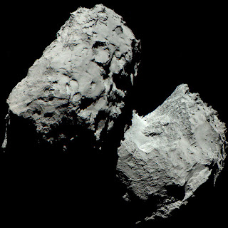
1.) For bodies that are not crazy differently from an ellipse/triaxial shape, the easiest method would be to use a best fit sphere. This is essentially what the IAU recommends for most odd bodies. Now for peanuts (or dumbbell) shaped bodies, this won't work too well (e.g. comet 67P/Churyumov-Gerasimenko or images from Rosetta).

2.) So for "peanuts", there has been research to take these irregular bodies and unwrap it for mapping applications. This generally means warping the irregular body into one Cartesian system (see: Stooke, Morphographic). As a graphic example, I like this video for unwrapping a face for a 3D texture in Blender - although sort-of creepy (see 10.5 minutes into the video).

3.) Others are testing methods to split up the body into multiple map projections. How to best split up the body would still be difficult and may require several different map projections to minimize large distortions for each part of the body. I think this might be explained for comet 67P by F. Preusker et al. but the paper is locked down. This seems the most reasonable solution since one can use well known map projection equations and applications will be able to still run stats (accurate measures) on the different parts. But displaying all the part together might be a challenge since they would essentially be defined as independent bodies. 

A color image of Comet 67P/Churyumov-Gerasimenko composed of three images taken by Rosetta's scientific imaging system OSIRIS. The images were taken on 6 August 2014 from a distance of 120 kilometres from the comet. Credits: ESA/Rosetta/MPS for OSIRIS Team MPS/UPD/LAM/IAA/SSO/INTA/UPM/DASP/IDA

I would love to hear other ideas for this topic.

-Trent


Wednesday, August 3, 2016

Does the NASA PDS image format make for a good interoperable format?


It could be but that is not its purpose in life.  This post was inspired by question, "why not make PDS exporting (or conversion from Geotiff) available from the NASA AMES Stereo Pipeline." This was my answer. Please note this is IMHO - please feel free to disagree.

background:

So I assume there are many PDS3 (and now some PDS4) writers out there. I actually don't know of a robust GeoTiff to PDS image converter. In general, I view the PDS (3 or 4) format as really an "archival" format and not necessarily a good format to support interoperability between applications. Okay so what's the difference? Archive formats are meant to be "simple" to use and should have verbose labels to access the data for years into the future. Sounds great - what's the problem? In particular, PDS archives can have metadata spread across multiple files which describe the mission, image label particulars, the map projection equations (which may not be  typical equations, if even map projected at all), etc., which makes a single image file less self-contained. Thus not only should a PDS *.IMG (image with label) be created, but to be a valid PDS archive, there should also be other informational files created in a structured set of directories. When GeoTiffs are used for archives (more common for Earth data sets), they actually have the same metadata problem, which is usually solved by using an FGDC/ISO metadata file sitting directly next to the GeoTiff (extension *.tif.xml).

Okay - I don't care about metadata, I just want to write out a PDS *.IMG format. Above, I stated there are probably dozen of PDS writers out there. The main reason there are so many is because the folks writing these files must target their labels for their particular mission. It would be a challenge to create a generic PDS label creation/conversion solution. Many portions of the required metadata cannot be 100% automated (whether PDS or FGDC metadata). For example for PDS, there are many keywords that the user should supply that would need to be (manually) defined during conversion (e.g. PRODUCED_ID, PRODUCER_FULL_NAME, INSTRUMENT_HOST_NAME, etc.). Check out any *.lbl from here.

All that said, both ISIS3 and VICAR can convert to a "generic" PDS v3 label, but it will not be a fully archive-able PDS label. To help with the mission particulars, you will notice ISIS3 has a unique PDS export routine for each instrument (when that instrument is supported for PDS export, e.g. lrocnac2pds, lrowac2pds, mrf2pds - https://isis.astrogeology.usgs.gov/Application/index.html#Lunar_Orbiter ).

Anyway, I am happy to share a very simple (hacky/brute force) gdal2PDS (v3) Python writer but it would need to be highly tweaked depending on the mission you are supporting. And I currently only support a couple projections as used by the LMMP project. Did I say it was very hacky -- use with caution: http://github.com/USGS-Astrogeology/GDAL_scripts/tree/master/gdal2ISIS3

Could a generic PDS3 writer be added to GDAL - yes. But PDS3 is slowly getting supplanted by PDS4 so that would need to be added too. PDS4 is XML based which can complicate simple writers. There are plans to add in a PDS4 reader to GDAL once the format stabilizes. A reader should be much more tangible than a generic writer (for map projected products at least). Heck, we could even support a "raw" Geotiff with a PDS 3 or 4 label pointing inside at the pixels, but raw Tiffs lose many benefits like tiles and compression capabilities.

-Trent

lots more information about PDS4: http://sbndev.astro.umd.edu/wiki/PDS4_Data_Structures

Sunday, July 17, 2016

more HiRISE conversion tips (until labels are fixed)

The HiRISE Team is still planning to fix a few label issues so these work arounds may go away.

background explanation for HiRISE projection issues - from wayback. See this post for more on how ISIS calculates a local scaling radius for equirectangular (aka equidistant cylindrical).

First you need to get some excellent DTMs (aka DEMs) and their orthorectified GeoJpeg2000 images: http://hirise.lpl.arizona.edu/dtm/

HIRISE label issues
(1) MOLA-orthorectified RDRs
For images without partnered DTMs (typical MOLA-rectified images), they have an older map projection definition (where std par is defined as the center lat). There is a simple script called "fix_jp2_v2" to switch the values in-place in the Jpeg2000 header. This updated version "v2" (Jan. 2023) can safely be run on older and newer (already corrected) HiRISE labels. For newer labels, the program will safely skip over them since they are corrected.

download source (fix_jp2_v2.cpp) or Windows binary (fix_jp2_v2.exe), readme.

original source code (now outdated. This version should not be used on newer HiRISE image as they are already corrected.): https://trac.osgeo.org/gdal/ticket/2706

> gcc -o fix_jp2_v2 fix_jp2_v2.cpp
> fix_jp2_v2 PSP_001918_1735_RED_C_01_ORTHO.JP2
Success, file updated.

(2) partnered DTM-orthorectified images
2.1. first run fix_jp2_v2 as in step 1.

2.2. So a more subtle issue (only in the partnered-DTM ortho-images *.JP2s), is that the radius is not set correctly in the geoJpeg2000 header. This doesn't impact the other map projection parameters (like cellsize or offsets) -- it is really just an incorrect value. To fix this for other GDAL environments you need to override the radius in the GeoJpeg2000 file (this generated vrt header also works for ArcMap).

using gdal tools you can create a corrected virtual header for the GeoJpeg2000 file using the projection defined in the DTM.
> gdalsrsinfo DTEEC_001918_1735_001984_1735_U01.IMG -o wkt > fixme.prj

>cat fixme.prj
PROJCS["EQUIRECTANGULAR MARS",GEOGCS["GCS_MARS",DATUM["D_MARS",SPHEROID["MARS_localRadius",3396040,0]],PRIMEM["Reference_Meridian",0],UNIT["degree",0.0174532925199433]],PROJECTION["Equirectangular"],PARAMETER["latitude_of_origin",0],PARAMETER["central_meridian",283.07],PARAMETER["standard_parallel_1",-5],PARAMETER["false_easting",0],PARAMETER["false_northing",0]]

>gdal_translate -of vrt -a_srs fixme.prj -a_nodata 0 PSP_001918_1735_RED_C_01_ORTHO.JP2 PSP_001918_1735_RED_C_01_ORTHO.vrt
Input file size is 6368, 10767

This process will work for the full-res "A" ortho files too, e.g. PSP_001918_1735_RED_A_01_ORTHO. I am also setting the image's nodata value in the command above too. Just helps with display.

------------------
BTW, if you don't like Jpeg2000 images you can use the HiRISE team JP2_PDS to convert to raw PDS format or the free Kakadu tools to convert to GeoTiff/GeoBigTiff. e.g.

> kdu_expand -i PSP_001918_1735_RED_C_01_ORTHO.JP2 -o PSP_001918_1735_RED_C_01_ORTHO.tif

-----------------

To map project these all to the same coordinate system (use the corrected vrt) and get the latest GDAL binaries and for each file run the lines below (for GDAL binaries, I like Anaconda Python environment [once installed type: 'conda install gdal'] or Kyng Chaos for Mac, or Osgeo4W - Windows). These steps should work for DTM *.IMG files also.

-only if you don't have GDAL with jpeg2000 support:
> kdu_expand -i PSP_001918_1735_RED_C_01_ORTHO.JP2 -o PSP_001918_1735_RED_C_01_ORTHO.tif
-- again fix radius for converted Tiff
> gdalsrsinfo DTEEC_001918_1735_001984_1735_U01.IMG -o wkt > fixme.prj
> gdal_translate -of vrt -a_srs fixme.prj PSP_001918_1735_RED_C_01_ORTHO.tif PSP_001918_1735_RED_C_01_ORTHO.vrt

in Degrees (equivalent ~1m/p):--download "Mars 2000 Sphere.prj"
> wget http://webgis.wr.usgs.gov/pigwad/ArcMap_prjs/Solar_System/Mars%202000%20Sphere.prj
> gdalwarp -t_srs "Mars 2000 Sphere.prj" -tr 1.70670654e-5 1.70670654e-5 -r bilinear PSP_001918_1735_RED_C_01_ORTHO.vrt PSP_001918_1735_RED_C_01_ORTHO_degrees.tif

Or in Meters (e.g. Simple Cylindrical or Equirectangular w/ center at 0, out cellsize set to 1m):
> echo 'PROJCS["Mars_Equidistant_Cylindrical",GEOGCS["Mars 2000",DATUM["D_Mars_2000",SPHEROID["Mars_2000_IAU_IAG",3396190.0,0]],PRIMEM["Reference_Meridian",0],UNIT["Decimal_Degree",0.0174532925199433]],PROJECTION["Equidistant_Cylindrical"],PARAMETER["False_Easting",0],PARAMETER["False_Northing",0],PARAMETER["Central_Meridian",0],PARAMETER["Standard_Parallel_1",0],UNIT["Meter",1]]' > Mars2000_Equi0.prj

> gdalwarp -t_srs Mars2000_Equi0.prj -tr 1 1 -r bilinear PSP_001918_1735_RED_C_01_ORTHO.vrt PSP_001918_1735_RED_C_01_ORTHO_1meter.tif

-------------------

Tip: To check out your handy work for the  DTM and fixed Ortho use TuiView or 3D Analyst. For 3D Analyst, simply load the images in and under the DTM and Ortho, set the Base Height Tab to use the DTM - almost instant 3D: https://pdsimage2.wr.usgs.gov/pub/pigpen/mars/tutorials/arcScene_Hirise.jpg